
Twisted pair
Twisted pair cabling is a form of wiring in which two conductors are wound together for the
purposes of canceling out electromagnetic interference (EMI) from external sources,
electromagnetic radiation from the UTP cable, and crosstalk between neighboring pairs.
wisting wires decreases interference because the loop area between the wires (which determines
the magnetic coupling into the signal) is reduced. In balanced pair operation, the two wires
typically carry equal and opposite signals (differential mode) which are combined by addition at
the destination. The common-mode noise from the two wires (mostly) cancel each other in this
addition because the two wires have similar amounts of EMI that are 180 degrees out of phase.
This results in the same effect as subtraction. Differential mode also reduces electromagnetic
radiation from the cable, along with the attenuation that it causes.
The twist rate (also called pitch of the twist, usually defined in twists per metre) makes up part of
the specification for a given type of cable. Where pairs are not twisted, one member of the pair
may be closer to the source than the other, and thus exposed to slightly different induced EMF.
here twist rates are equal, the same conductors of different pairs may repeatedly lie next to each
other, partially undoing the benefits of differential mode. For this reason it is commonly specified
that, at least for cables containing small numbers of pairs, the twist rates must differ.In contrast to
FTP (Foiled Twisted Pair) and STP (Shielded Twisted Pair) cabling, UTP (Unshielded Twisted Pair)
cable is not surrounded by any shielding. It is the primary wire type for telephone usage and is
very common for computer networking, especially as patch cables or temporary network
connections due to the high flexibility of the cables.
Unshielded twisted pair (UTP)
Twisted pair cables were first used in telephone systems by Bell in 1881 and by 1900 the entire
American network was twisted pair, or else open wire with similar arrangements to guard against
interference. Most of the billions of conductor feet (millions of Kilometres) of twisted pairs in the
world are outdoors, owned by telephone companies, used for voice service, and only handled or
even seen by telephone workers. The majority of data or Internet connections use those wires.
UTP cables are not shielded. This lack of shielding results in a high degree of flexibility as well as
rugged durability. UTP cables are found in many ethernet networks and telephone systems. For
indoor telephone applications, UTP is often grouped into sets of 25 pairs according to a standard
25-pair color code originally developed by AT&T. A typical subset of these AD1L colors
(white/blue, blue/white, white/orange, orange/white) shows up in most UTP cables.
For urban outdoor telephone cables containing hundreds or thousands of pairs, different twist
rates for each pair are impractical. For this design, the cable is divided into smaller but identical
bundles, with each bundle consisting of twisted pairs that have different twist rates. The bundles
are in turn twisted together to make up the cable. Because they reside in different bundles, twisted
pairs having the same twist rate are shielded by physical separation. Still, pairs having the same
twist rate within the cable will have greater crosstalk than pairs of different twist rate. Thus to
minimize crosstalk within a large cable, careful pair selection is important.
Twisted pair cabling is often used in data networks for short and medium length connections
because of its relatively lower costs compared to fiber and coaxial cabling.
Uses
Unshielded twisted pair (UTP) cabling, because of its 100-year history of use by telephone
systems, both indoors and out, is also the most common cable used in computer networking. It is
a variant of twisted pair cabling. UTP cables are often called ethernet cables after Ethernet, the
most common data networking standard that utilizes UTP cables, although not the most reliable.A
telephone line or telephone circuit (or just line or circuit within the industry) is a single-user circuit
on a telephone communications system. Typically this refers to the physical wire or other
signaling medium connecting the user's telephone apparatus to the telecommunications network,
and usually also implies a single telephone number for billing purposes reserved for that user.
In 1876 the earliest lines were single electrically conducting metal wires directly connecting one
telephone to another with the Earth forming the return circuit. Later in 1878 the Bell Telephone
Company ran lines (called the local loop) from each user's telephone to end offices which
performed any necessary electrical switching to allow voice signals to be transmitted to more
distant telephones.
These wires were typically copper, although aluminium has also been used, and were carried in
pairs separated by about 25cm (10") on poles above the ground, and later as twisted pair cables.
Modern lines may run underground, and may carry analog or digital signals to the exchange, or
may have a device that converts the analog signal to digital for transmission on optical fiber or
other carrier system.In most cases, two copper wires (tip and ring) for each telephone line run
from a home or other small building to a local telephone exchange. There is a central junction box
for the building where the wires that go to telephone jacks throughout the building and wires that
go to the exchange meet and can be connected in different configurations depending upon the
subscribed telephone service. The wires between the junction box and the exchange are known
as the local loop, and the network of wires going to an exchange, the access network.Most
houses in the U.S. are wired with 6 position modular jacks with four conductors wired to the
house's junction box with copper wires. Those wires may be connected back to two telephone
lines at the local telephone exchange, thus making those jacks RJ14 jacks. Mor exchange as one
telephone line, and the others are unconnected. In that case, the jacks in the house are RJ11.
Historical note
Soon after the invention of the telephone, open wire lines were used for transmission. Two wires,
strung on either side of cross bars on poles, share the route with electrical power lines. At first,
interference from power lines limited the practical distance for telephone signals. Discovering the
cause, engineers devised a method, called wire transposition, to cancel out the interference,
where once every several poles, the wires crossed over each other. In this way, the two wires
would receive similar EMI from power lines. Today, such open wire lines with periodic
transpositions can still be found in rural areas. This represented an early implementation of
twisting with a twist rate of about 4 twists per kilometre.A utility pole, telegraph pole, telephone
pole, power pole, or telegraph post is a post or pole upon which telecommunication network
equipment is situated. They originally prevented telegraph wires from being short circuited, and
continue to protect surface traffic from being inconvenienced by cables and vice versa. They are
often also used for electrical cables (with pylons being used for only the higher voltage
applications) and frequently a pole will share both power and communications lines. Telegraph
poles first became commonplace in the middle 19th century, carrying at first one steel wire, then
in urban areas many. In Canada, the poles are commonly referred to as hydro poles, as the
electric companies commonly have "Hydro" in their name.
Most utility poles are made of wood pressure-treated with some type of preservative to keep away
woodpeckers, insects, fungi, and fires. Many different types of trees can be used to make utility
poles, including Douglas fir, Jack Pine, Lodgepole Pine, and Pacific Silver Fir. Western Red Cedar
is also popular for its natural insecticidal properties and durability, though its higher price deters
many utility companies. Other common utility pole materials are steel and concrete, with
composites (fibreglass) also becoming more prevalent. In some countries, for example the UK,
poles have sets of brackets arranged in a standard pattern up the pole to act as hand and foot
holds for those working on the equipment or connections atop the pole. In the USA such steps are
usually provided only for the upper part of the pole; the worker normally uses climbing spikes to
reach them.The appearance of poles has changed with technology through the 20th Century, with
for example the loss of the stereotypical but now redundant crossbeam used to mount rows of
insulators for open wire telephone circuits. These more traditional poles can sometimes be seen
unaltered beside non-electrified railways, or where no effort has been made to remove
crossbeams not in use.
Utility pole
A utility pole, telegraph pole, telephone pole, power pole, or telegraph post is a post or pole upon
which telecommunication network equipment is situated. They originally prevented telegraph wires
from being short circuited, and continue to protect surface traffic from being inconvenienced by
cables and vice versa. They are often also used for electrical cables (with pylons being used for
only the higher voltage applications) and frequently a pole will share both power and
communications lines. Telegraph poles first became commonplace in the middle 19th century,
carrying at first one steel wire, then in urban areas many. In Canada, the poles are commonly
referred to as hydro poles, as the electric companies commonly have "Hydro" in their name.Today
utility poles may hold much more than the uninsulated thin copper wire that they originally
supported. Thicker cables holding many twisted pair lines or coaxial cable or even fibre-optics
may be carried. Simple analogue repeaters or other outside plant equipment have long been
mounted against poles, and often new digital equipment for multiplexing/demultiplexing or digital
repeaters may now be seen. In many places, as seen in the illustration, providers of electricity,
television, telephone, street lighting, traffic signals and other services share poles, either in joint
ownership or by renting space to each other. Such poles provide a safe gap between power lines
on top and signal wires below.Wooden utility poles and railroad ties are almost always treated with
creosote to slow decomposition. This is also the most common way of preserving wood in the
United States.Throwing poles similar to utility poles is a traditional Scottish sport known as the
caber toss.
The appearance of poles has changed with technology through the 20th Century, with for example
the loss of the stereotypical but now redundant crossbeam used to mount rows of insulators for
open wire telephone circuits. These more traditional poles can sometimes be seen unaltered
beside non-electrified railways, or where no effort has been made to remove crossbeams not in
use.However in the countries of Eastern Europe, in Russia and in countries of the third world,
there are still many utility poles carrying bare wires mounted on insulators not only along railway
lines, but also along roads and sometimes even in urban areas. Errant traffic being uncommon on
railways, their poles are usually less tall. In the UK, many wooden poles carry electricity from super
pylons to the user at lower voltages (240 V to 11 kV depending on type, Cable shieldingand often
in three phases). The conductors on these are bare metal connected to the posts by insulators.
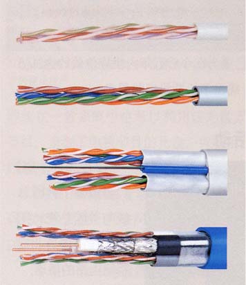
Cable shielding
Twisted pair cables are often shielded in attempt to prevent electromagnetic interference.
Because the shielding is made of metal, it may also serve as a ground. However, usually a
shielded or a screened twisted pair cable has a special grounding wire added called a drain wire.
This shielding can be applied to individual pairs, or to the collection of pairs. When shielding is
applied to the collection of pairs, this is referred to as screening. The shielding must be grounded
for the shielding to work.STP cabling includes metal shielding over each individual pair of copper
wires. This type of shielding protects cable from external EMI (electromagnetic interferences). e.g.
the 150 ohm shielded twisted pair cables defined by the IBM Cabling System specifications and
used with token ring networks.S/STP cabling, also known as Screened Fully shielded Twisted Pair
(S/FTP),[1] is both individually shielded (like STP cabling) and also has an outer metal shielding
covering the entire group of shielded copper pairs (like S/UTP). This type of cabling offers the best
protection from interference from external sources.
Electromagnetic interference (or EMI, also called radio frequency interference or RFI) is a (usually
undesirable) disturbance caused in a radio receiver or other electrical circuit by electromagnetic
radiation emitted from an external source. [1] The disturbance may interrupt, obstruct, or
otherwise degrade or limit the effective performance of the circuit. The source may be any object,
artificial or natural, that carries rapidly changing electrical currents, such as an electrical circuit,
the Sun or the Northern Lights.EMI can be induced intentionally for radio jamming, as in some
forms of electronic warfare, or unintentionally, as a result of spurious emissions and responses,
intermodulation products, and the like. It frequently affects the reception of AM radio in urban
areas. It can also affect cell phone, FM radio and television reception, although to a lesser extent.
Power line noise
Virtually all power-line noise, originating from utility company equipment, is caused by a spark or
arcing across some power-line related hardware. A breakdown and ionization of air occurs, and
current flows between two conductors in a gap. The gap may be caused by broken or loose
hardware such as a cracked insulator. Typical culprits include insufficient and inadequate
hardware spacing such as a gap between a ground wire and a staple. Once an ionized path is
established in the gap, current flows at all parts of the cycle where the voltage is higher than the
breakdown voltage of the gap. This typically occurs only at the positive and negative voltage
peaks -- the times of highest instantaneous voltage throughout the cycle.
As an example for a 60Hz system (i.e.power-lines carrying 60 Hz AC, such as in the US), the
voltage on them passes through two peaks each cycle (one positive and one negative) and pass
through zero twice each cycle. This gives 120 peaks and 120 zero crossings in each second
(50Hz: 100 peaks and crossings correspondingly). Power-line noise follows this pattern, generally
occurring in bursts at a rate of 120 bursts per second. This gives power-line noise a characteristic
sound that is often described as a harsh and raspy hum or buzz. Because the peaks occur twice
per cycle, true power-line noise has a strong 120-Hz modulation on the signal (50Hz system:
100Hz).EMI or RFI may be broadly categorized into two types; narrowband and broadband.
Narrowband interference usually arises from intentional transmissions such as radio and TV
stations, pager transmitters, cell phones, etc. Broadband interference usually comes from
incidental radio frequency emitters. These include electric power transmission lines, electric
motors, thermostats, bug zappers, etc. Anywhere electrical power is being turned off and on
rapidly is a potential source. The spectra of these sources generally resembles that of
synchrotron sources, stronger at low frequencies and diminishing at higher frequencies, though
this noise is often modulated, or varied, by the creating device in some way. Included in this
category are computers and other digital equipment as well as televisions. The rich harmonic
content of these devices means that they can interfere over a very broad spectrum. Characteristic
of broadband RFI is an inability to filter it effectively once it has entered the receiver chain.
Mitigation
On integrated circuits, the most important means of reducing EMI are: the use of bypass or
"decoupling" capacitors on each active device (connected across the power supply, as close to
the device as possible), risetime control of high-speed signals using series resistors, and VCC
filtering. Shielding is usually a last resort after other techniques have failed because of the added
expense of RF gaskets and the like.
The efficiency of the radiation depends on the height above the ground or power plane (at RF one
is as good as the other) and the length of the conductor in relation to the wavelength of the signal
component (fundamental, harmonic or transient (overshoot, undershoot or ringing)). At lower
frequencies, such as 133 MHz, radiation is almost exclusively via I/O cables; RF noise gets onto
the power planes and is coupled to the line drivers via the VCC and ground pins. The RF is then
coupled to the cable through the line driver as common-mode noise. Since the noise is
common-mode, shielding has very little effect, even with differential pairs. The RF energy is
capacitively coupled from the signal pair to the shield and the shield itself does the radiating. One
cure for this is to use a braid-breaker or choke to reduce the common-mode signal.
At higher frequencies, usually above 500 MHz, traces get electrically longer and higher above the
plane. Two techniques are used at these frequencies: wave shaping with series resistors and
embedding the traces between the two planes. If all these measures still leave too much EMI,
shielding such as RF gaskets and copper tape can be used. Most digital equipment is designed
with metal, or conductive-coated plastic, cases.Switching power supplies can be a source of EMI,
but have become less of a problem as design techniques have improved.Most countries have
legal requirements that mandates electromagnetic compatibility: electronic and electrical hardware
must still work correctly when subjected to certain amounts of EMI, and should not emit EMI which
could interfere with other equipment (such as radios). Susceptibilities of different radio
technologies.
Susceptibilities of different radio
technologies
Interference tends to be more troublesome with older radio technologies such as analogue
amplitude modulation, which have no way of distinguishing unwanted in-band signals from the
intended signal, and the omnidirectional dipole antennas used with broadcast systems. Newer
radio systems incorporate several improvements that improve the selectivity. In digital radio
systems, such as Wi-Fi, error-correction techniques can be used. Spread-spectrum and
frequency-hopping techniques can be used with both analogue and digital signalling to improve
resistance to interference. A highly directional receiver, such as a parabolic antenna or a diversity
receiver, can be used to select one signal in space to the exclusion of others.
The most extreme example of digital spread-spectrum signalling to date is ultra-wideband (UWB),
which proposes the use of large sections of the radio spectrum at low amplitudes to transmit
high-bandwidth digital data. UWB, if used exclusively, would enable very efficient use of the
spectrum, but users of non-UWB technology are not yet prepared to share the spectrum with the
new system because of the interference it would cause to their receivers. The regulatory
implications of UWB are discussed in the Ultra-wideband article.